A retake on the Porter Springfield mount
Some thoughts on Springfield mounts.
Hands up! How many of you have knees that don’t bend like they used to? How about backs that don’t like twisting and bending?
I’ve seen a lot of ads over the last few years about people selling off their gear because of health issues – usually related to carting their gear around, setting up, and tearing gear down again. Even a pier-mounted equatorial in an observatory requires that you still contort. And you have to admit, once you reach a certain age, the glow comes off this part of our hobby…
Well, here is a possible solution.
What if you could set up once, and after that, simply sit in your seat and observe? And if this telescope mount was GOTO, then even better. Even if you had to set up only once per observing session, it would be beguiling, but if you had an observatory, where everything was as you left it last session, it would be nirvana…
So I got to thinking (as my wife tells me, a dangerous pastime), what about a Porter –Springfield (PS) GOTO mount?
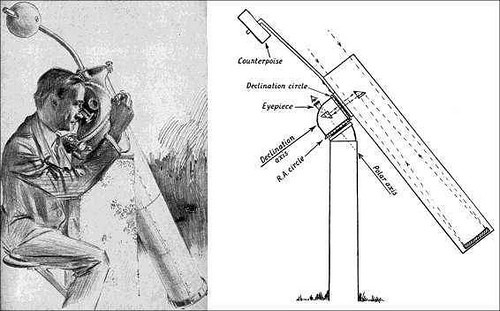
For those of you unfamiliar with the PS mount concept, it is an equatorial mount that projects its light cone thru a hollow declination axis to be intercepted by a secondary mirror coincident with the RA axis. In this fashion, the EP always stays centered around intersection of the RA and Declination axis’s and so, no matter where the scope points, the EP remains stationary.
This means you can sit down at the eyepiece, and no matter where the scope points, you don’t have to shift position. Add GOTO to this and you have the answer to all your doctors and chiropractors’ cautions.
After researching Springfield mounts, a few things became obvious:
- You need a fair amount of back focus depending on the mount design.
- If you use a Newtonian with a fixed image plane (as in the pic above), longer focal lengths are necessary in order to obtain the necessary ‘back focus’ without an unduly large secondary mirror. And because the bulk of the Newtonian is effectively revolving around where the focuser would normally be, heavy and cumbersome counterweights at the opposite ends/sides are necessary to counterbalance the OTA in both RA and dec. Short focal length Newtonians ie” less than F8/F10) are not practical due to the oversized secondary obstruction necessary to intercept the light path close enough to the primary to ‘project’ it out to the PS focal plane.
- Refractor tubes would need to be shortened to free up the necessary back focus necessitated by the PS design.Longer focal length refractors are more suitable as their narrow light cone is easier to field and keeps the downstream component diameters reasonable. Also, the bulk of the scope would be out front, necessitating that the CWs go below – the opposite of the Newtonian above.
- SCT’s are perfect in as much as their moving mirror focus mechanism means you can compensate for differences in focal plane easily, and their typical F10 light cone is easy to field. Like the refractor, the CW’s end up being below.
- There was an interesting article about how to intercept the light cone from the secondary half way down the baffle tube with a tertiary secondary ( a secondary secondary..??) and bounce it off to the side down a hollow declination axis housing. Credit for this idea must go to Ed Johnston whose similarly modded SCT can be found here: http://www.flickr.com/photos/edhiker/sets/72157624186145557
Although I sacrificed a dilapidated B&L8000 to this proof of concept (it did work), I felt it was a lot more intrusive than most people would feel confortable committing to – even if it was reversible (with some scarring mind you..) So I experimented with how to employ a variant that required no changes to the SCT OTA.
- Standard mounts do not lend themselves to PS use because they do not have the necessary hollow DEC axis to pass the light cone.
So following are the trials and tribulations of fabricating a GOTO Springfield mount.
Construction techniques.
What limited Springfield resources exist show dedicated castings being machined.
This is not within my, or most other peoples, capabilities. So I chose to make mine out of slabs of ½” and 1/4 “ aluminum. Aluminum is remarkably easy to cut with a miter saw and a carbide blade. A little WD40 or paraffin wax along the cut line results in a nice clean cut.

However, you will either need a metal lathe or have access to someone that does to make some of the necessary components.
The real design trick is to keep the Dec. bearing thickness to a minimum in order to limit the back focus necessary. Any bearing type will work for the polar/RA axis, but I chose to make it hollow to provide for a polar alignment scope.
I chose to go with ‘plate bearings’ on both axis. This design offers wide bearing diameters for stability while keeping the thickness to a minimum.
Design and implementation notes;
I am not a mechanical engineer, so I based my material selections based on what I thought would be strong enough. I decided on ½” plates 6x6” square. This provided a bearing diameter of about 5”. (I believe in the brick shi#*&$ house design principal)
The thrust bearings used are readily available on eBay and cheap. They’re available in a wide range of diameters and are nice and thin – approx.. 4mm.


I machined a groove in matching sets of 6x6x1/2” aluminum plate so serve as bearing races. In retrospect, I could just have easily used a larger set of the same type of plate bearings I used for the axis hold-down thrust bearings - just larger in diameter. But I have a lathe and 4 chunks of aluminum was a lot cheaper than a couple of 5” diameter needle thrust bearings.
It’s a lot easier to purchase worms and gears than to attempt making them. They come up fairly regularly on the Astro sites, orphans from various deceased equatorial fork mounts..
The original PS design had a fixed diagonal on top of the RA housing near the eyepiece that could be adjusted for tilt/tip. I opted to forgo this and instead opted to use a couple of standard 90* star diagonals. One in the OTA tailpiece, and one in the declination axis provide the necessary ‘alignment’. If you’re out a bit, it will show up as a bit of field rotation when slewing.

I used nylon thumbscrews in the dec axis diagonal so it could be ‘snugged, but was still free to slip and maintain its vertical position (other wise, it would turn with the dec axis..). I introduced a couple of locating pegs to prevent it rotating.
My design requires counterweights both in Dec in RA. I’m still cogitating about this. The RA CW is really only in the way for N. observing. For anywhere south of the pier, it’s out of the way.
This design is scalable. A larger aperture SCT would only require more offsetting counterweights in Dec and RA. I’m not sure how much back focus would be available on larger aperture SCTs. After all, they all use the same accessories - so you may have the same designed in back focus, but require another 2-3” light path to clear the larger diameter OTA. My design requires about 6” of additional back focus to accommodate the PS mount, plus ½ of the OTA diameter….
Focusing is currently achieved by reaching the SCT focus knob – it’s not far away on the 6”. I’m thinking of working out a flexible focusing cable so I can use the SCT focus for everything. The Celestron C6 focuser is sublime and doesn’t need a lot of torque…
The other option would be to use a helical focuser in the final star diagonal ahead of the eyepiece. Use the SCT focuser to set the average focus and then use the helical for fine focus.
This method allows any SCT to be adapted to a PS type mount without any alteration to the OTA. I am not an optical engineer, but what little I have read (and understood) on the web indicates that varying the back focus this much may introduce spherical aberration into the image. Also, some vignetting at the primary baffle tube may occur as the primary moves closer to the secondary in order to ‘throw’ the image plane backwards by the required amount.
I will have to do some testing and comparisons, but initial tests indicate that there is some vignetting as the image is dimmer. I also think that a relay lens about half way down the 10.5” PS light path might eliminate/reduce this vignetting by allowing the image palne to remain close to where the factory specs called for it to be. If there’s anyone out there with some suggestions, I’d love to hear from you.
I’ve still got to fit worm gears for slo mo and axis locks to make the mount more user friendly. The original shot of the bare aluminum mount showed a set of Meade LS gears fitted, but I ended up selling those – but it shows how/where they mount. I’m awaiting another set coming in.
I’ll then see about adapting a set of Meade DS motors and 497 controller to make it GOTO per Patrick Bedair’s robo-scope website here. www.bedair.org
But listen up all you telescope manufacturers out there! – We old guys collectively represent a large demographic that all have the same problem – we’re getting old….A commercialized Porter Springfield mount could be your next big thing!
Funding Member