
Hypertuning A Celestron AVX Mount

Hypertuning my Celestron AVX
This article was written and submitted by Patrick Stevenson.
This question eventually surfaces on just about every mount found in the low to medium range. If you pay $6,000 for a mount it has probably been Hypertuned during manufacturing. For a mount like the AVX what you get is an assembled piece of machinery that is simply bolted, snapped, or screwed together and never really tested or adjusted for fine operation. That is why your mount is usually stiff or tight. I recently bought a new Advanced VX mount as a part of my down-sizing program.
When I opened the box I was really excited to try it out. I set up the tripod in my den and put the mount in place. I sort of read the manual; I have, after all I had a number of previous mounts so I figured I knew what I was doing. Assembly complete it was time to try it out, but first a little hands on check for function.
I was a bit surprised at how really tight the DEC axis was. With no weight on it I could only get it to move by pushing it. I rotated the axis so the counterweight bar was parallel to the floor and let it go. It just stayed there. I tried manually getting it to rotate. It only went as far as I pushed it. Now it was time to try the RA axis. Not surprisingly, it was the same; Very stiff and hard to move.
My first thought was the clutch knob was probably too tight so I removed the plastic cover and loosened the brass fixture until it actually came out. So, the clutch might still be the problem. I tried the same manual tests and had the same results. At that point there was nothing left to do but actually energize the mount and check the axes movements.
I applied power, turned on the switch, followed the prompts on the hand paddle until I could manually choose movements. The DEC axis moved smoothly with no strange noises, as did the RA axis. Okay, due diligence was done and it was time to try it out with my new SkyWatcher Evostar 100ED. I couldn’t wait for dark.
By 2000hrs it was plenty dark and M42 was clearly visible. I ran my StarSense protocol and everything seemed to work fine. I tried a test of the GOTO by choosing Capella. WOW! Right in the center of my Frame and Focus in my Backyard EOS. I focused to about 3.5 and then slewed to M42 for a full-function test. I set the camera for 50 frames at 120”/ISO800 and waited.
When the run was finished I took my laptop into my den and downloaded all of my CR2 (RAW) files to PixInsight Blink to cull out any bad frames. I lost 15 frames because of “rice” stars. All the other frames were perfect. Upon closer examination is appeared that I would get a series of about five frames perfectly and then one bad one. Then about five more perfect followed by a bad one. Patterns intrigue me. If something repeats, it will generally be easier to diagnose than a random problem.
I am not a Mechanical Engineer but it seemed to me that the mount was storing energy trying to overcome the stiffness of the mount and when the energy level got high enough, it unloaded and the mount skipped. At least it seemed logical and certainly fit with my previous observations regarding the tightness of the two axes.
I looked and looked to try and find a diagram of the mount construction but to no avail. I then called Ed at Deep Space Products (deepspaceproducts.com) where some year back I had gotten Hypertune kits for my Atlas EQ-G mounts. Unfortunately, they do not carry any kits or instructions for the AVX mount. They do carry replacement bearings for the worm gears, but that is all. My previous experience with Hypertuning Atlas mounts taught me that replacing the worm gear bearing is difficult and frankly not necessary.
I finally resorted to YouTube. You can find everything on YouTube. Sure enough, there were three videos on Hypertuning the AVX mount. I really hate to make disparaging remarks about what other’s do, but in this case I must. Although I did learn a lot from the videos I was horrified at what they did to those poor little mounts. Firstly, it looked like Bubba working on his lawnmower on the garage floor. “Proper tool for the proper job” was apparently unknown to these folks. “Just give me a claw hammer and chisel!” In one video the viewer is told that “This plastic piece always gets broken, don’t worry about it.”
I just paid $900 for this pretty little mount and I am NOT going to beat it into submission with a hammer! Way over in China on an assembly line these mounts are carefully assembled to pass Quality Control inspections. I doubt they use hammers to assemble them. It is important to note that the mounts are assembled, not tuned. So, I took what good I learned from the videos and proceeded.
For this project you will see WARNING and NOTE. The warning is when damage to the unit is possible. Note is just a suggestion that might make things easier.

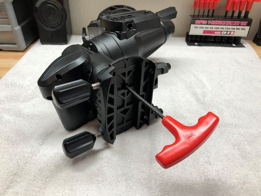
I placed my pretty little mount on my work table in my den (no garage floors for MY mount). I gathered my tools, a pad and pen, and went to work. I first removed the Polar Alignment adjusters, along with the latitude adjuster bolt and counter weight bar. I removed these primarily just to get them out of the way. I also removed the DEC axis connection cable. I set these aside out of the way since I would not need them again until after I was done.

I saw that the DEC axis was attached to the mount with only two allen head bolts. So, I decided to start with the DEC axis. First I removed the four allen head bolts that secure the telescope mounting plate.
You will notice that I practice a convention that I learned building and racing cars. When I remove a bolt or screw to take something apart I always put the screws back in the holes they came from. That way I don’t have bolts and screws of different sizes cluttering my work place. By the way, it makes reassembly much easier when the screws and bolts are already where they are supposed to be.

(Notice the allen bolts back in the holes they came from.)
WARNING: Be very careful not to damage the machined mating surfaces both on the top of the axis and inside the bottom of the telescope mounting device.
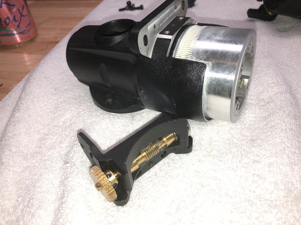
I then removed the two allen bolts attaching the DEC axis and replaced the bolts.

At this point you can clear your workspace and leave only the DEC axis.

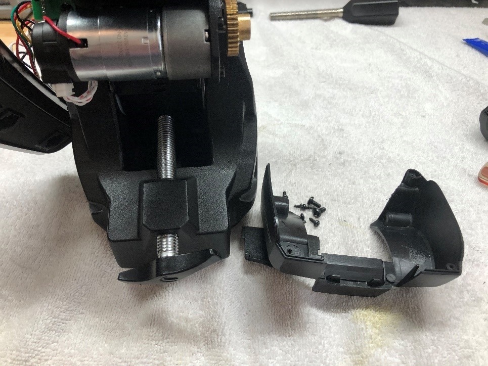
Remove the small Phillips screws that hold the plastic covers that shield the DEC motor. You won’t be able to put these screws back in the hole easily so set them aside in a container so they don’t get lost.
NOTE: Whenever you run across one screw that is different than the others be sure to note it on your workpad.


WARNING: There is a small circuit card attached to one of the covers that has wires going to the motor. Be sure to unplug the connector before you remove the cover.

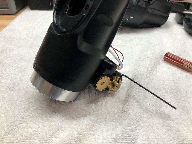
Once the plastic covers are removed and set aside the DEC motor is exposed and the straight-cut gears that turn the worm gear are apparent.
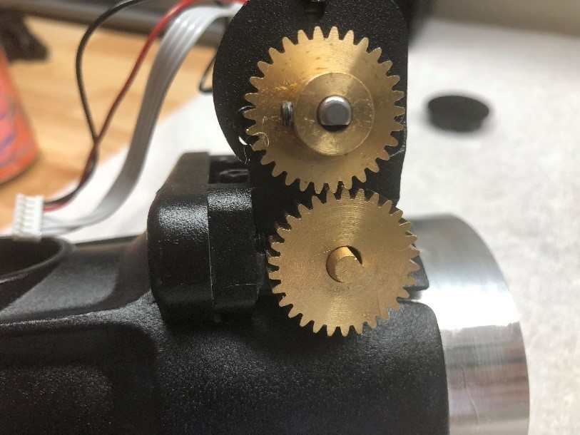
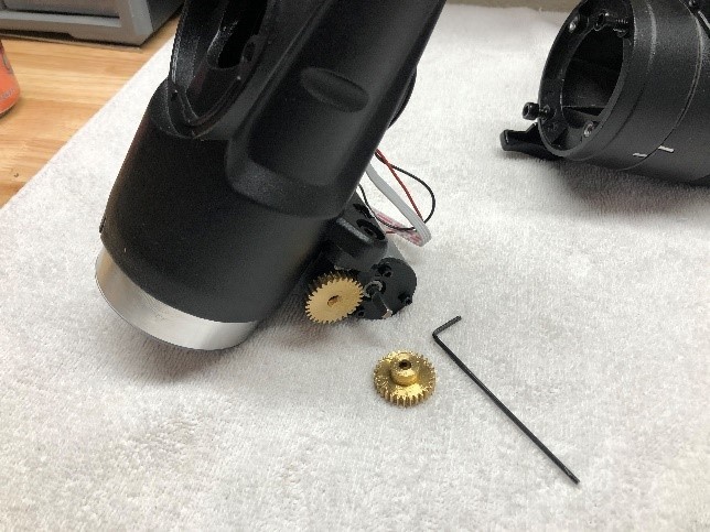
It is time to remove the motor from the housing. It is kind of like a Chinese puzzle which will be apparent, however I will try to help out with some ideas. The first thing you want to do is remove the motor gear. There are two allen set screws that you must loosen and the gear will slide right off.
NOTE: You may be concerned at this point about how the mount knows where it is. There is a decoder that will establish it’s position when it is reassembled so you don’t need to worry about getting things back exactly where they were. This will be covered later.
Notice that there are three small allen screws holding the motor in place. I will explain clearly how this apparatus is reassembled later. At this point, just go ahead and remove the motor.
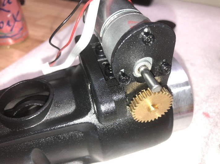
Removing the worm gear may seem complicated but it is quite easy. We will cover reassembly later including proper meshing of the worm to the ring gear; another major cause of backlash.


There are four allen head bolts that hold the worm gear in place. You will notice that there is a small allen head set screw located between two of the bolts. That small screw is what adjusts the mating of the worm and ring gear. You don’t need to mess with that screw now. That will be covered in reassembly.
You can now lift the worm gear out of position revealing the ring gear. There is no reason to mess with the straight-cut gear on the end of the worm gear unless you are replacing bearings, which I don’t do.
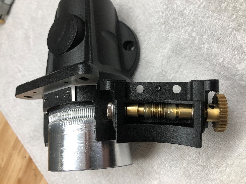
WARNING: Be very careful handling the worm and ring gears. They are precisely machined to match and any damage will cause major problems.
NOTE: Since I already did this whole project before disassembling for this project I cleaned all the Chinese grease out and replaced it with lithium. Your mount may have lots of heavy grease (They seem to be very proud of it). Be sure to use a good solvent (I used MEK) to remove all the grease and regrease using a light soft grease. Use lots in the worm gear housing to get it into the bearings.
There is a clear plastic spacer on top of the ring gear. It may be hard to see because of the grease. Be sure to set it aside for cleaning but always keep it in the vicinity of the ring gear so you won’t forget it on reassembly. This is a good spot to use your workpad.
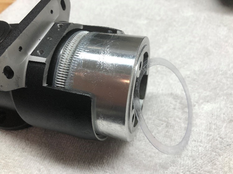

You can now slide the ring gear out of the housing.
WARNING: All of these nice shiny surfaces are meticulously machine for clearance. Any dings or scratches should be considered major damage.
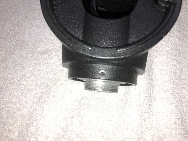
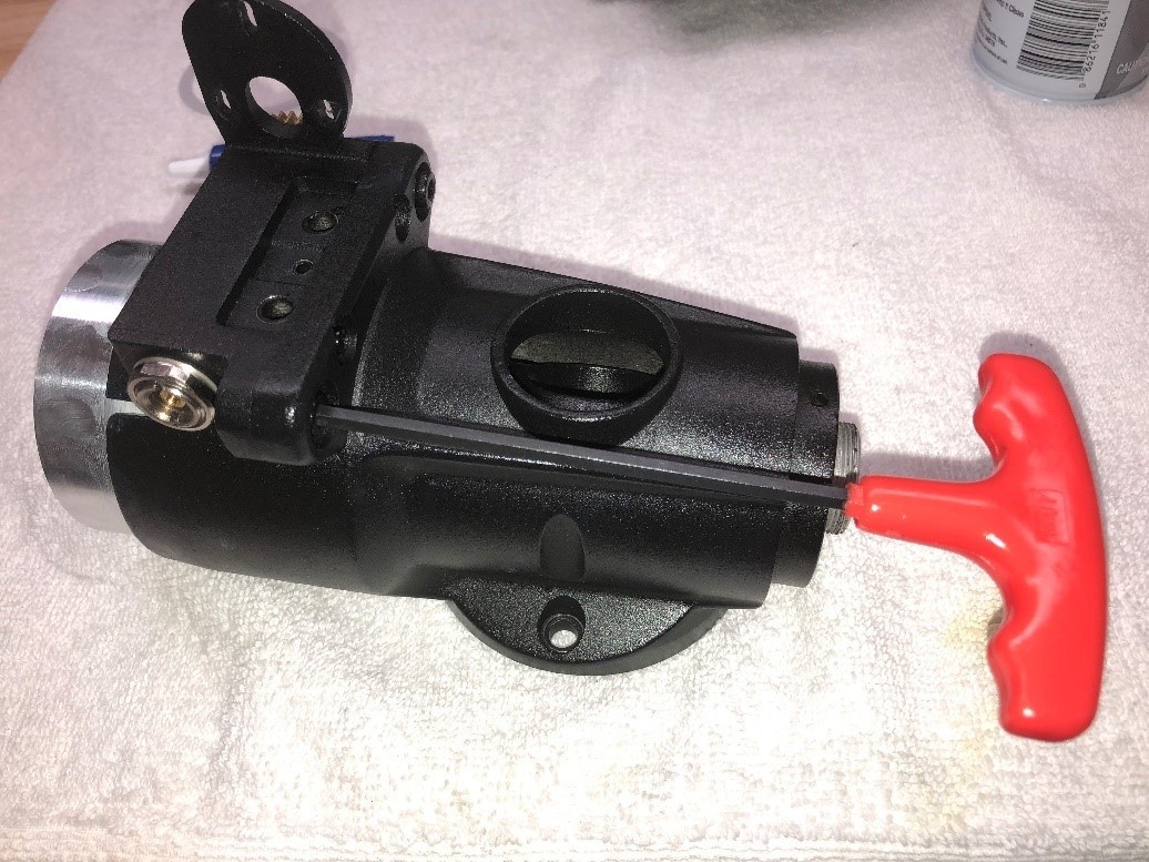
Having removed the ring gear it is time to remove the DEC axis shaft. It is held in place by a threaded collar that screws down on the end of the shaft. Look closely at the base of the housing and you will see a small hole. By rotating the shaft you will find three allen set screws that lock the collar in place. Loosen each allen screw but not so far that the allen screw sticks out above the collar.


The collar has two indented holes 180 degrees apart. Using snap ring pliers or some other tool to loosen the collar. If it does not come off easily be sure all the set screws are loose.

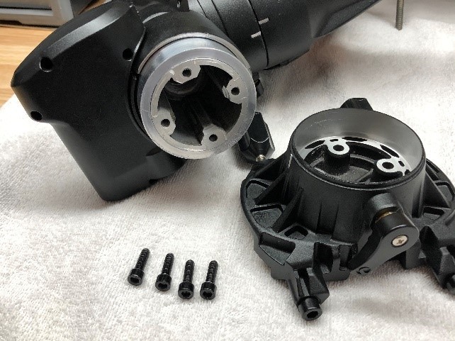
As the collar comes off you will find a “stack” that is comprised of nylon spacers and a ball bearing. This pictures shows what all is going to fall out the bottom of the housing.
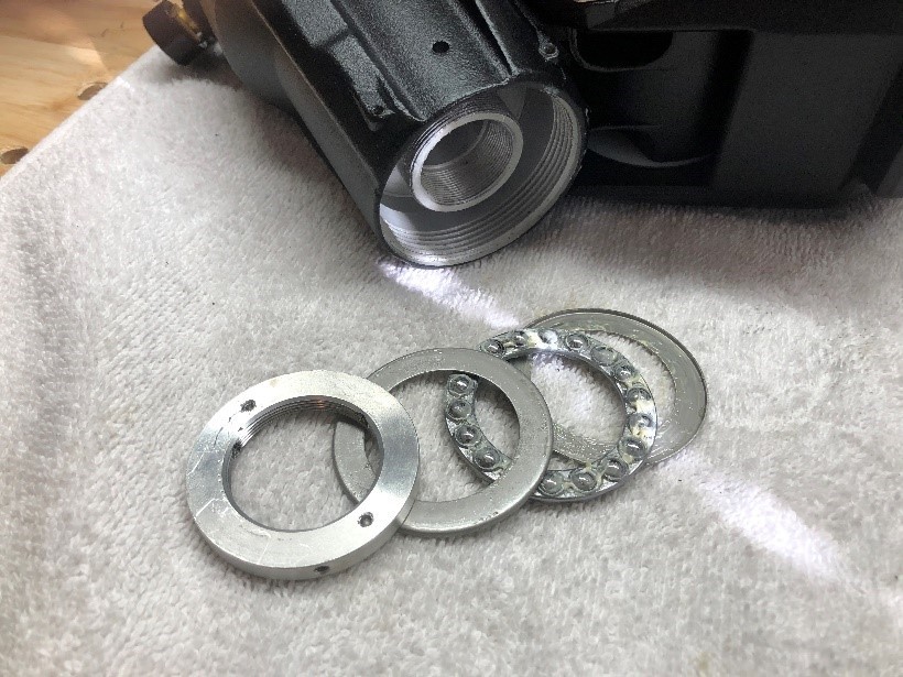
This bearing does not support weight, or even align the shaft. It simply allows the shaft to turn after the collar is tightened to hold everything together.
You will note as you inspect each machined surface that it has a mating surface. The machined tolerance is set to allow a grease film to keep the two from coming into physical contact. There are three things that can be done to increase performance of a mount like this. 1. Clean all old grease and replace with a white lithium or equivalent grease. Only use enough to ensure a film on each surface. 2. Polish mating machined surfaces. Machining leaves a microscopic rough surface. That will cause “drag” on the metal. Polishing does not change the machine tolerances but microscopically smooths the surface to reduce “drag”. 3. Carefully tighten the collar so that it does not cause any binding. This is done by feel alone. It is a balance between easy rotating and push-pull on the shaft to make sure there is no “play”.

A dremel tool with a polishing bit will work just fine or a bench grinder with a polishing wheel will work as well. I don’t use a bench grinder because they create enough torque that I have destroyed machined surfaces because they got away from me.

I will not document reassembly because it is literally doing everything backward. I am, however, going to dedicate some time to mating and tuning the worm gear to ring gear and the motor gear to worm gear. These two are critical and contribute the most to backlash.
It should be noted, and fully understood, that bearings in a telescope mount are only there to support weight. These are not wheel bearings that turn 5,000rpm’s. Over the course of an evening’s use a bearing may not even rotate once. When you are told that you need to machine out the housing and insert a Timken tapered bearing, that simply is not true. Certainly not on this mount. The only exception is that you will find that the RA axis on the AVX does have a sealed bearing on its shaft. That will be covered in the RA section.
TUNING THE GEARS
Examining the ring gear is critical because there may be a problem with some of the teeth or in the machining. This is important because the ring gear will never travel more than 180 degrees. If you find a bad spot you can position the ring gear so that spot never comes in contact with the worm gear. Before greasing the ring gear you should use an air compressor, or in my case, canned air to blow out all old grease, polishing compound, and any particulates. This should be done after polishing but before your final grease.

Clean the ring gear with solvent, dry thoroughly, and apply a thin layer of grease on the outside. On the inside you will see a small raised band at the top and bottom. These are the only two places that need grease. Apply grease more generously to the ring gear teeth being sure that each one gets grease.

Be sure the worm gear is greased thoroughly, enough to work its way into the bearings. Since I did not replace the worm gear bearings I do not cover that operation. It is fairly obvious how to do it and you can buy replacement bearings from www.deepspaceproducts.com , although I didn’t feel it was necessary.
Remember that there are four bolts that attach the worm gear assembly to the housing which will mesh the worm gear and the ring gear. Install all four bolts until they are barely snug and then loosen ½ turn.
Alternately tighten the two bolts on the front of the assembly. As you do, manually spin the gear on the shaft until you see the ring move. If you tighten too much you will bind the worm against the ring and it will lock up. It is a juggling act to loosen and tighten the two bolts until you don’t feel any slop but the ring gear moves readily as you spin the worm gear. That little center set screw is what will ultimately set the mesh. By snugging down the two bolts and tightening the little set screw you will reach the point where the slightest movement of the worm gear will cause the ring gear to move. This is a good spot to use a magnifying glass of sorts so you can detect the very slightest movement. Any movement of the worm gear that does not immediately cause the ring to move is backlash. Once all of that is snugged down go ahead and tighten the last two bolts, as shown. Keep checking back to ensure that the worm and ring mesh without any backlash and are not binding.

Mount the motor to the worm gear assembly using all three allen screws. If you put the drive gear on the motor shaft at this point you will notice that two of the mounting screws are behind the gear. That is why those two screws must be left loose. Leave the motor gear off for now.

At this point adjust the two gear teeth so they mesh completely with no slop (backlash). Tighten the one screw that is available, remove the gear and tighten the last two screws and replace the gear. Check again that there is no slop and that the gears are not too tight against each other. It may take a couple of tries but the effort is well worth it. When this operation is complete, plug the motor control wire back into the circuit card inside the plastic cover and VOILA, you have tuned your mount. Now simply reassemble the mount by following instructions in reverse. Each time you reattach something keep checking for smooth movement so you do not introduce a problem. At the completion of reassembly, make sure your clutch is loose and you will find that the DEC axis will move MUCH more easily. Set the DEC assembly aside, grab a refreshment, and get ready to start on the RA axis. You will find that there are so many components that are the same or similar that the RA axis will be much easier.
Reassembly problems I had:
Only one. When I slid the ring gear over the shaft bushing it would not go low enough to mate the ring gear and worm gear. I tried many times to no avail. I finally just sat and looked at it for awhile. I knew something was keeping the gear from sliding all the way on. I checked to make sure the clutch was out of the way. It turns out that the clutch lever, which is bronze, doesn’t touch the ring. There is a small plastic button that fits in the hole where the clutch lever fits. It had come out and was the interference. I removed the bronze clutch, fished out the button and put it back in the hole, reinserted the bronze lever, adjusted the depth and it was fixed. Boy, was I dumb. Other than that it went back together like a breeze.
Right Ascension Axis
Almost immediately you will notice the similarities to the DEC axis. As such, I will concentrate on those things that are unique to the RA axis. The main difference in design and construction is that the RA shaft rides on a sealed bearing which we will address later. The reason there is a bearing on the shaft is that the weight of the DEC axis, Telescope and accessories ride on the end of the shaft.

We will start by removing the plastic piece that contains all of the communication ports on the side of the mount. There are five phillips screws securing the panel, four of which screw into the metal housing and one smaller screw that secures the mount to the upper DEC motor cover.


You will find a small wiring harness that plugs into a circuit card inside the upper plastic cover. Removing the top plastic panel will reveal the DEC motor and the encoder. The wire harness plugs into the back of the encoder. Unplug and set the panel aside.

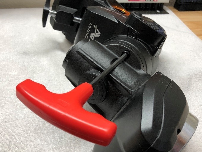
Removing the upper cover is quite straightforward. The lower one is the tough one. This is the one that the YouTube video says “everyone” breaks it. It wasn’t broken when it was installed and I was determined not to break it taking it apart. I don’t have any specific moves to share, just be patient. You will have to twist and stretch but it WILL come out. It has a small trap door that I’m sure has a purpose but I couldn’t find it.

See? It does come out!

WARNING: Be very careful working around the encoder. This device tells the mount where it is at any time. You will see a disc with a slot. As the disc rotates the slot allows light through and tells the mount where it is. Don’t worry if you move the disc, it will calibrate itself after assembly.

You will notice that the motor drive for the worm gear is almost exactly like the DEC axis so I will not go into detail here. The only real difference is the two lower allen bolts are harder to get to and require a longer wrench.
If you have a Polar Scope this would be a good time to remove it.
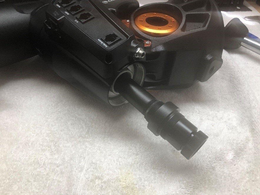
The “tail” of the RA axis is very much like the DEC axis. The hole in the housing that allows you to loosen the set screws in the collar is located under the plastic panel so you won’t see it until the panel is removed.

The end appearance is pretty much like the DEC axis

Once the collar is removed you can turn the axis right side up and a “stack” like the DEC axis should fall out. On this axis you will also find a plastic spacer that must be put back in the right order.

WARNING: You may find at this point that the shaft containing the ring gear will slide out without removing the worm gear. You may even think like me that I won’t have to remove the worm gear at all. Not so. The ring gear will not slide back in without removing the worm gear. Trying may cause damage to both the ring and worm gears.
Removing the worm gear is just like the DEC axis so I won’t detail that here. From now on you can pretty much follow the same procedures you did on the DEC axis. Remove all the old grease and regrease using something like lithium. Watch for plastic spacers. There are more on this axis and you don’t want to mix or miss any. Here is the biggest difference between the two axes; the bearing.

This is the bearing that the YouTubers will tell you to replace with a more expensive, even a tapered bearing. That is a waste of time and effort, and may even damage your mount. This bearing is designed to carry a “side” load and barely rotates. Replacing this bearing with a high rpm racing bearing is ridiculous. It is already sealed so you don’t even have to worry about lubing it. I would keep solvents away because they may seep past the seals.
At this point you can conduct your cleaning, polishing, and regreasing all the machined surfaces. Reassemble in reverse order. When you get to the “breakable” plastic cover don’t give in to thinking it doesn’t really matter. This is a precise machine that deserves the best. I actually took the drive gear off the motor to give a bit more room that worked great. I then put the gear back on and tightened the set screws.

I would recommend taking your own pictures as you work. A video would even be nicer to have.
-Patrick Stevenson
Funding Member