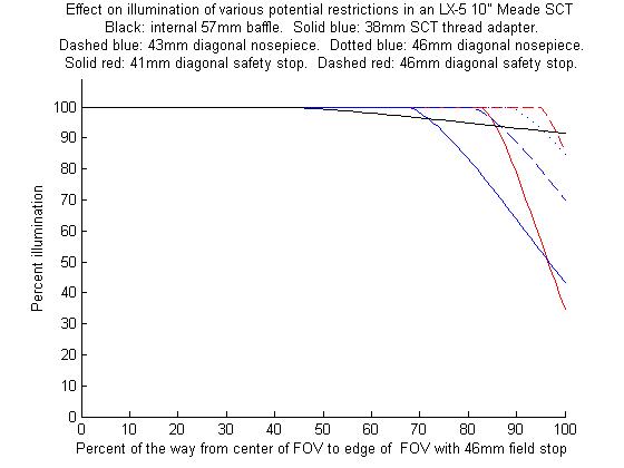
I made the attached plot of the illumination percent across the FOV, from center to edge, for the case of the maximum field stop of 46mm. There is a separate line on the plot for each of 6 potential restrictions, which are listed in the plot label. The plot was produced with a short MATLAB code I wrote, and is based on the approx. geometry of my 10" Meade. The results depend on the exact dimensions and positions of things. I measured where possible, but a few had to be estimated, so here are the numbers I used.
secondary mirror: 75mm diam. 625mm from field stop
baffle: 57mm inside diameter, ends 425 from field stop
38mm adaptor/43mm nosepiece/46mm nosepiece: Inside diameter 38/43/46mm respectively. In all cases 100mm from field stop.
41mm eyepiece stop/46mm eyepiece stop: Inside diameter 41/46mm respectively. In both cases 50mm from field stop.
The results are based on how much of the secondary mirror is blocked by the various obstructions. The calculation is done for each of 100 points equally spaced along an "equator" across the field stop from center to edge. The resulting 100 values are connected to produce the lines in the plot. The calculation of the percent of the secondary visible is very tedious since ray tracing or intuition shows a crescent shaped section is what gets blocked. The area of the crescent is computed with a difference between two "area of a circle cut off by a chord" calculations. The two relevant circles are the secondary itself, and the circular area that is visible through the restriction from the relevant point along the field stop equator. Basically, where the two circles overlap, the secondary is visible and where they don't overlap, the restriction is eclipsing a crescent shaped portion of the secondary. The visible area (total - crescent) as a percentage of the total area of the secondary is what is given as the "percent illumination"
Note that the line for the baffle drops below 100% illumination first, meaning the baffle is what limits the fully illuminated portion of the field. However the other obstructions block light more aggressively nearer to the edge.
Disclaimer: I'm not an optics expert so I can't say with 100% certainty that my method is foolproof and that my plot is accurate. It's just my best effort at a pretty tedious calculation and for what it's worth I don't know of any reason why it wouldn't be accurate...
secondary mirror: 75mm diam. 625mm from field stop
baffle: 57mm inside diameter, ends 425 from field stop
38mm adaptor/43mm nosepiece/46mm nosepiece: Inside diameter 38/43/46mm respectively. In all cases 100mm from field stop.
41mm eyepiece stop/46mm eyepiece stop: Inside diameter 41/46mm respectively. In both cases 50mm from field stop.
The results are based on how much of the secondary mirror is blocked by the various obstructions. The calculation is done for each of 100 points equally spaced along an "equator" across the field stop from center to edge. The resulting 100 values are connected to produce the lines in the plot. The calculation of the percent of the secondary visible is very tedious since ray tracing or intuition shows a crescent shaped section is what gets blocked. The area of the crescent is computed with a difference between two "area of a circle cut off by a chord" calculations. The two relevant circles are the secondary itself, and the circular area that is visible through the restriction from the relevant point along the field stop equator. Basically, where the two circles overlap, the secondary is visible and where they don't overlap, the restriction is eclipsing a crescent shaped portion of the secondary. The visible area (total - crescent) as a percentage of the total area of the secondary is what is given as the "percent illumination"
Note that the line for the baffle drops below 100% illumination first, meaning the baffle is what limits the fully illuminated portion of the field. However the other obstructions block light more aggressively nearer to the edge.
Disclaimer: I'm not an optics expert so I can't say with 100% certainty that my method is foolproof and that my plot is accurate. It's just my best effort at a pretty tedious calculation and for what it's worth I don't know of any reason why it wouldn't be accurate...
Attached Image: