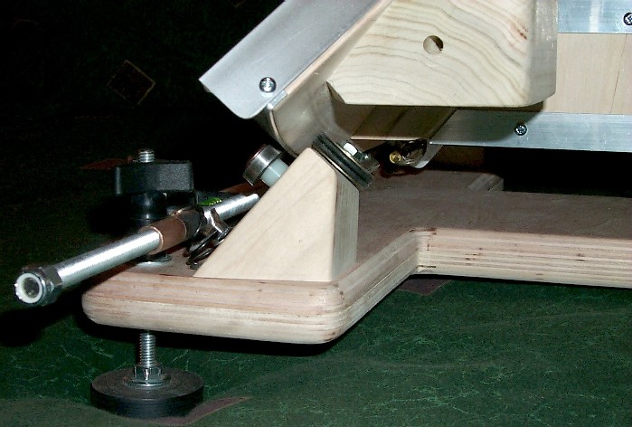
Thought I'd share the finished project.
Here's an assessment of the pros and cons of this design, as I've found so far:
Pros:
- Very powerful, weight/imbalance tolerant drive system
- Strong, backlash free linkage
- Resets instantly by disengaging drive rod from a half-nut
Cons:
- Some periodic error unless leadscrew and connection to motor shaft are perfectly straight
- Tangential error common to all tangent driven platforms
After straightening the threaded rod and making the best rod to motor shaft connector I could, the platform has a small amount of periodic error--which admittedly caught me by surprise. It will move an object around approximately 1/3 of the apparent field of my highest power eyepiece (4mm ortho--305x) in my 8" f/6 newtonian every 45 or so seconds. So, it's not a photography-capable platform as currently driven.
But... I insisted on instant reset and weight/center-of-gravity tolerance (and design simplicity)--these objectives it achieves. Traditional tangent drives are cumbersome to reset and direct drives are sensitive to weight and center-of-gravity issues. In short, I don't like periodic error, but I'd take a small amount over lengthy reset procedures or a slipping table.
I am considering eventually driving the platform using a variation of the linear conversion drive shown via the link below. I imagine instead a timing belt doing a continuous loop while forcefully engaging/disengaging the belt via a clutch where the current pivot (brass thumbscrew) is located. I would also insist that any drive system employed retain fast reset and variable load tolerance.
http://faculty.washington.edu/quarn/stpmtr.html
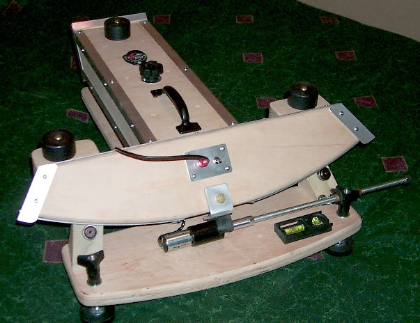
Here's an assessment of the pros and cons of this design, as I've found so far:
Pros:
- Very powerful, weight/imbalance tolerant drive system
- Strong, backlash free linkage
- Resets instantly by disengaging drive rod from a half-nut
Cons:
- Some periodic error unless leadscrew and connection to motor shaft are perfectly straight
- Tangential error common to all tangent driven platforms
After straightening the threaded rod and making the best rod to motor shaft connector I could, the platform has a small amount of periodic error--which admittedly caught me by surprise. It will move an object around approximately 1/3 of the apparent field of my highest power eyepiece (4mm ortho--305x) in my 8" f/6 newtonian every 45 or so seconds. So, it's not a photography-capable platform as currently driven.
But... I insisted on instant reset and weight/center-of-gravity tolerance (and design simplicity)--these objectives it achieves. Traditional tangent drives are cumbersome to reset and direct drives are sensitive to weight and center-of-gravity issues. In short, I don't like periodic error, but I'd take a small amount over lengthy reset procedures or a slipping table.
I am considering eventually driving the platform using a variation of the linear conversion drive shown via the link below. I imagine instead a timing belt doing a continuous loop while forcefully engaging/disengaging the belt via a clutch where the current pivot (brass thumbscrew) is located. I would also insist that any drive system employed retain fast reset and variable load tolerance.
http://faculty.washington.edu/quarn/stpmtr.html
Attached Image: