Image of the day

Captured by
John Roach

Enhanced Uranus showing Polar Cap and possible Aurora

My Account

New to Astromart?

Register an account...

Need Help?

Wrapping Up Another One

Started by P. Lee Stock, 05/10/2004 04:37PM
Posted 05/10/2004 04:37PM Opening Post
Just thought I'd share some cell and power supply photos from my latest project...

Lee


Attached Image:

P. Lee Stock's attachment for post 15795
Posted 05/10/2004 04:39PM #1
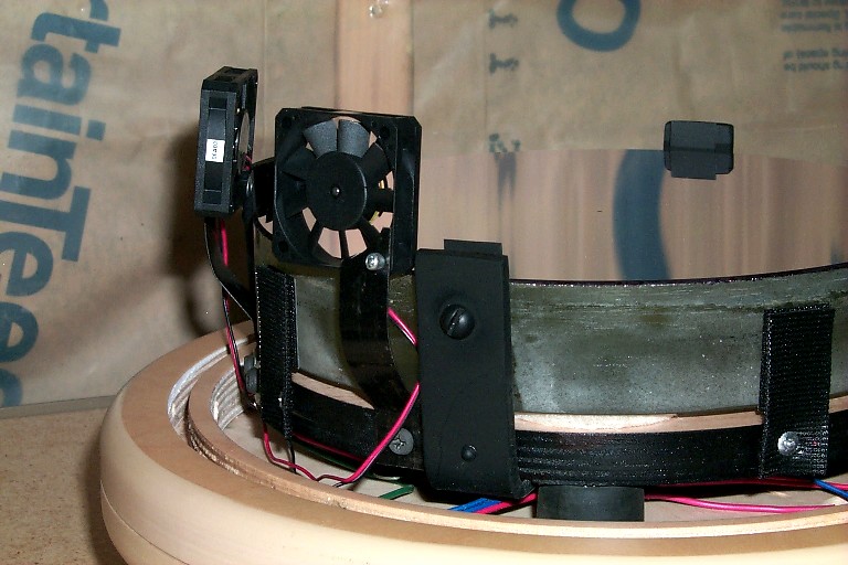
Boundary layer fans mounted on steel banding strap material and positioned just off the edge of the mirror. Single rear-mounted fan is in a downdraft configuration to pull the air down and out the tube (tube current management) while also pulling the boundary layer air out the back that has just been pushed off the edge of the mirror. Fans are on variable speed, individually controlled circuits.


Attached Image:

P. Lee Stock's attachment for post 79541
Posted 05/10/2004 04:46PM #2
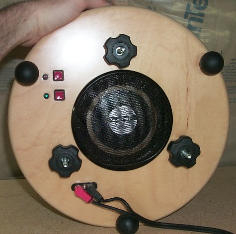
Overview of the power supply and mirror cell. A 5.75" x 3" x 2" Radio Shack project box contains a 1.2Ah 12v battery and all power switching variable speed controls required to run the fans from full stop through full power on high and low speed settings.

Power supply weighs around 3 or 4 lbs. and will velcro to the outside of the tube and act as an adjustable counterweight.

Rear tube ring (half-ring) slips over the back end of the tube and is attached by screws. Back plate with cell attached unscrews and is removable separately from tube ring (Richard Berry style).


Attached Image:

P. Lee Stock's attachment for post 79542
Posted 05/10/2004 04:50PM #3
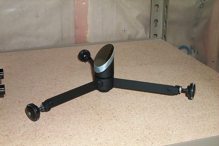
Secondary mirror mount made from 6/6 nylon turned on a minilathe and steel banding strap material riveted to the center hub. Hooked vane ends are bathroom mirror hangers/clips.

Secondary mirror is a 1/20-wave part from Antares. Primary mirror is a pick-of-litter Mike Spooner mirror I bought from our local forum friend, Rob O'Toole. Mike wrote the word "Wow!" on the back of the mirror, so I am guessing this will be a nice scope when it's finished ;^).


Attached Image:

P. Lee Stock's attachment for post 79543
Posted 05/10/2004 04:55PM #4
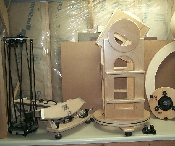
And finally, here is the completed mount. All I have left is to finish the tube--and I'm almost done with that too. The EQ platform I made last autumn.


Attached Image:

P. Lee Stock's attachment for post 79544
Posted 05/11/2004 04:53PM #5
Never mind, Lee. I see from another one of your posts that the back plate is two pieces. It all makes sense now! ;^)

Doug


Hey, Lee, I have a question regarding how you plan on mounting the bottom plate to the tube. It looks like you've used a router to "machine" a circular groove in the end plate, to receive the tube. But once you insert the tube, how will you fasten it together? Once it's together, you can't reach inside to insert any screws. You can’t be using glue, ‘cuz then you’ll never get it apart.

Love your attention to detail, like the recesses for the pushbuttons and indicator lights.

Doug
Posted 07/13/2004 01:44PM | Edited 07/13/2004 03:35PM #6
Hey, Lee, I was thinking of using your cell design in my next project. But I was thinking of fixing the mirror to the rear plate (using spacers of some sort for air circulation around the mirror), and using the three outboard bolts that fix the rear plate to the one attached to the tube as the collimation screws. I would sandwich some weather stripping foam between the plates to make an air-tight seal yet allow for movement when collimating. Any thoughts on this? Did you ever consider it but reject it for one reason or another?

Thanks,
Doug