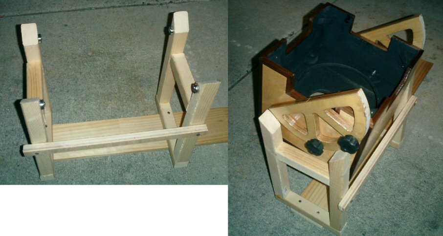
We had that recent thread on how to position the focal plane relative to your focuser travel, so I thought I'd post this.
I made this tool to help with the problem of determining the ideal primary mirror/cell location in a tube. Most modern newtonian focusers are low profile and have drawtubes with a travel range somewhere between 1-1/4" to 1-5/8" or so, which means you really only have 1/4" or so of room for error when positioning the focal plane relative to the focuser/drawtube travel or many eyepieces out there won't come to focus within the range of your focuser.
When assembling the components of a tube, I first install the focuser and then the secondary mirror assembly. Then, after leaving the tube intentionally long, I insert this into the back, flush with the end. With my trusty TV plossl (I bought one just for this purpose), I take the telescope out under the stars and advance the primary mirror using the extremely long screws until stars come to focus. This tells me exactly where to position the cell.
When I mess up and get the primary too close to the secondary, I get to make a brand new tube since my cells attach to a back plate that attaches to an end ring, Richard Berry style. I hate that. When others get it wrong, they either have to drill new holes for the mirror cell, or new holes for the focuser and spider, or make a riser block for the focuser. Why guess?
The reason for using a TV eyepiece for this function is explained here:
http://astromart.com/messages.asp?message_id=180100&page=
This one is for 10" mirrors. I suppose I could have made one that adjusts for 8", 10" and 12.5", but I went the separate tools method instead. Note that it has very long travel. There are nails set into the wedge blocks that grab the tube wall for peace of mind. I wouldn't trust friction alone.
If you are making just one scope, then this is overkill. But if you are planning to make a few in your life, this is far better than guessing where the focal plane will wind up and being completely wrong, or having your son peek through your Nagler while you sit on the ground with a mirror in one hand and a measuring tape or pencil in the other asking "are they points yet?" That got tired.
Cloudy Skies!! (TM'ing weather)
Lee
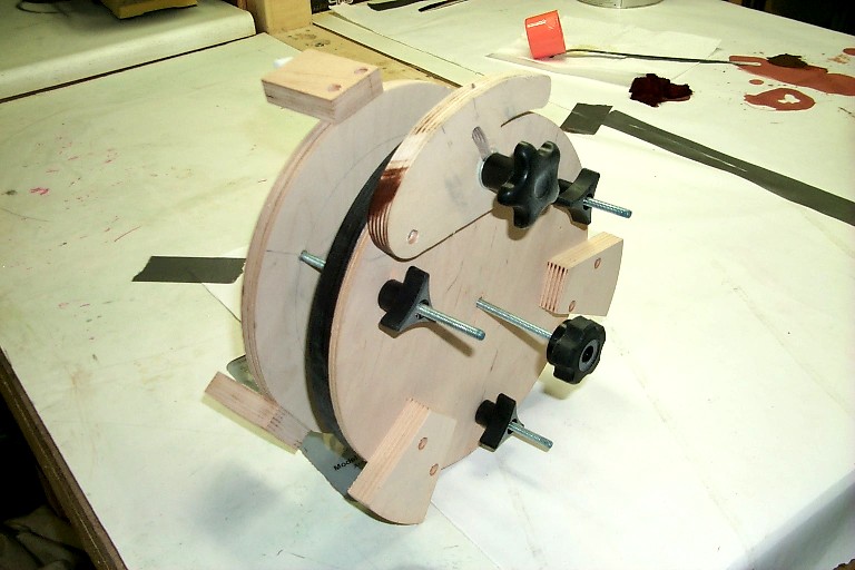
I made this tool to help with the problem of determining the ideal primary mirror/cell location in a tube. Most modern newtonian focusers are low profile and have drawtubes with a travel range somewhere between 1-1/4" to 1-5/8" or so, which means you really only have 1/4" or so of room for error when positioning the focal plane relative to the focuser/drawtube travel or many eyepieces out there won't come to focus within the range of your focuser.
When assembling the components of a tube, I first install the focuser and then the secondary mirror assembly. Then, after leaving the tube intentionally long, I insert this into the back, flush with the end. With my trusty TV plossl (I bought one just for this purpose), I take the telescope out under the stars and advance the primary mirror using the extremely long screws until stars come to focus. This tells me exactly where to position the cell.
When I mess up and get the primary too close to the secondary, I get to make a brand new tube since my cells attach to a back plate that attaches to an end ring, Richard Berry style. I hate that. When others get it wrong, they either have to drill new holes for the mirror cell, or new holes for the focuser and spider, or make a riser block for the focuser. Why guess?
The reason for using a TV eyepiece for this function is explained here:
http://astromart.com/messages.asp?message_id=180100&page=
This one is for 10" mirrors. I suppose I could have made one that adjusts for 8", 10" and 12.5", but I went the separate tools method instead. Note that it has very long travel. There are nails set into the wedge blocks that grab the tube wall for peace of mind. I wouldn't trust friction alone.
If you are making just one scope, then this is overkill. But if you are planning to make a few in your life, this is far better than guessing where the focal plane will wind up and being completely wrong, or having your son peek through your Nagler while you sit on the ground with a mirror in one hand and a measuring tape or pencil in the other asking "are they points yet?" That got tired.
Cloudy Skies!! (TM'ing weather)
Lee
Attached Image: